Tag Archives: usa printed circuit boards

rework your pcb

Reworking Your Defective PCBs?

Did You Know That We Can Also Rework Your Defective PCBs?

When you put in a large order for printed circuit boards from a PCB assembly service provider, you may find that a few circuit boards are defective in each bunch. Rather than write these circuit boards off as a loss (and lose your investment), you may be able to give them new life.

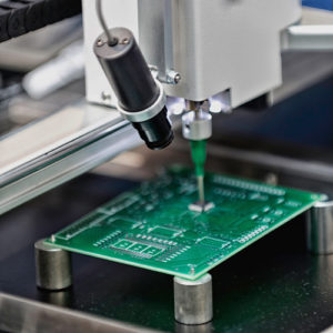
At ACME PCB Assembly, we may be able to re-work and repair some defective printed circuit boards. Often, this requires de-soldering and re-soldering components. This is manual work that must be performed by a trained technician. Fortunately, we have highly qualified staff members who can perform these repairs for you. This way, you don’t have to write off so many PCBs and can re-coup at least some of your costs.

PCB repair and rework services are an essential a process as manufacturing. Ensuring that any design flaw or damaged PCB component is repaired immediately will help maintain the PCB’s performance. In addition to these services, we conduct functional tests on your PCBs after the repair work is completed. This is performed to ensure that the device is running as per application and industry requirements.

We closely match new incoming inquiries to board house equipment and capabilities, ensuring you receive only those inquiries that you are interested in Acme Circuit board assembly provide PCB fabrication service in the development and manufacturing of quality single, double sided and Multi-Layers printed circuit boards for the computer, medical, transportation, communication, aircraft, aerospace and related industries.

At ACME PCB Assembly, we take full responsibility for your printed circuit board order. This means we that we use only ACME PCB Assembly certified suppliers as our offshore partners.

Want to see what we can do? Contact us today to learn more about our PCB repair and modification services.

Printed circuit board production

Surface Mount Technology (SMT) vs. Through-Hole Technology: Pros and Cons

In the ever-evolving world of electronics manufacturing, choosing the right assembly method is crucial for optimizing both performance and cost-efficiency. Two prominent techniques in this realm are Surface Mount Technology (SMT) and Through-Hole Technology. Each has its own advantages and drawbacks, making it essential to understand their unique characteristics and applications.

Printed circuit board productionSurface Mount Technology (SMT) has become the industry standard due to its efficiency and versatility. SMT involves mounting electronic components directly onto the surface of printed circuit boards (PCBs). This method significantly enhances the automation potential, allowing for high-speed production and reduced labor costs. The compact nature of SMT components enables the design of smaller and lighter devices, a crucial factor in modern electronics where space and weight are at a premium.

One of the key benefits of SMT is its superior performance in high-frequency applications. The reduced lead length in SMT components minimizes the parasitic inductance and capacitance, leading to better signal integrity and faster operational speeds. This makes SMT the preferred choice for complex and high-speed circuits commonly found in telecommunications, computing, and consumer electronics.

However, SMT is not without its challenges. The smaller component size can make manual handling and inspection difficult, necessitating advanced automated inspection systems. Additionally, SMT components are generally less robust in terms of mechanical strength compared to their through-hole counterparts, which can be a consideration in applications subject to high mechanical stress.

On the other hand, Through-Hole Technology has been a staple in the industry for decades. This method involves inserting component leads through pre-drilled holes in the PCB and soldering them on the opposite side. The primary advantage of through-hole technology is its mechanical stability. The strong solder joints created by this method are highly reliable, making it ideal for applications where durability and longevity are paramount.

Through-hole technology also excels in high-power and high-voltage applications. The robust nature of the components allows them to handle greater electrical currents, making through-hole technology indispensable in industries such as automotive, aerospace, and industrial equipment. Additionally, through-hole components are easier to handle and inspect manually, which can be beneficial for prototyping and low-volume production.

Despite its strengths, through-hole technology has its limitations. The manual insertion process is labor-intensive and time-consuming, leading to higher production costs and longer assembly times. The requirement for drilled holes also reduces the available space on the PCB for routing signals, potentially limiting design flexibility and increasing the board size.

In conclusion, the choice between SMT and through-hole technology depends on the specific requirements of your project. For high-speed, high-density, and cost-sensitive applications, SMT offers unparalleled advantages. Conversely, for high-reliability, high-power, and mechanically robust applications, through-hole technology remains a superior choice. Understanding the pros and cons of each method allows manufacturers to make informed decisions that align with their production goals and application needs.

For more detailed information on our SMT assembly services, visit our Surface Mount Technology Assembly page. Explore how we can help you leverage the strengths of SMT to achieve your project objectives.

Printed Circuit Board Fabrication

What You Actually Need to Make a Printed Circuit Board?

What Do You Actually Need to Make a Printed Circuit Board?

Printed circuit boards are in all manner of electronics. If it has computing power, then it is likely to include a printed circuit board. What is a PCB actually made of, and what components does it include? Surprisingly, PCBs are not too complicated.

The first ingredient you’ll need is the printed circuit board itself. The board won’t be of much use until you assemble it. To do that, you’ll need electronic components, soldering materials, soldering flux, and the soldering equipment.  Using the soldering equipment, printed circuit board assemblers, like Acme PCB Assembly, solder on the electronic components. The soldering equipment includes things like solder wire, solder paste, solder bar, and solder performs.

The Components Involved in Printed Circuit Boards

If the copper traces behave like the skeleton of the PCB, acting like the basic structure – then the components are the vital organs. Each component used has a different function. Using all these different components gives the circuit the unique qualities that it needs to fit for its intended purpose. Depending on what the device is or what the electronic item is, a PCB is designed for a variety of different components that will be needed for different circuits. These components can consist of a wide range of electronic parts. Some common PCB components include:

Battery: Provides the voltage to the circuit.

Resistors: Control the electric current as it passes through them. They’re color coded to determine their value.

LED’s: Light emitting diode. Lights up when current flows through it, and will only allow current to flow in one direction.

Transistor: Amplifies charge.

Capacitors: These are components which can harbor electrical charge.

Inductor: Stores charge and stops and change in current.

Diode: Allows current to pass in one direction only, blocking the other.

Switches: Can either allow current or block depending if they are closed or open.

Of course, there’s a lot more to printed circuit board assembly, but we’re not about to give away all of our secrets! If you want to work with a trusted and experienced printed circuit board assembler, contact us today!